The paparazzi controller was derived from the autopilot one.
It is composed of two stacked boards.

- Unstacked boards

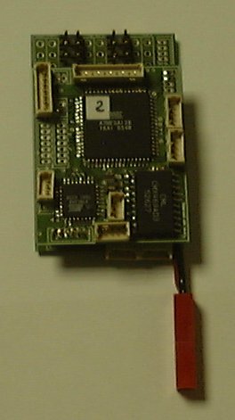
- Top view
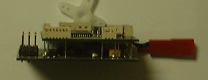
- Side view
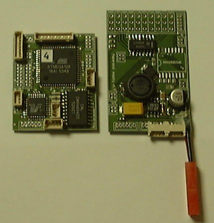

Top board
It is the CPU board and it is common to every applications. It has two atmel mega MCUs, one mega8 and one mega128 both running at 16 MHz and one modem.- The mega8 is responsible for PPM decoding, servos driving and auto/manual switching. It is connected to a commercial rc receiver
- The mega128 runs the rest : data acquisition/filtering, control loops, navigation and mission control, telemetry communications. It is connected to the GPS, the infrared sensor and the modem
The modem is still the old CMX469 FSK 1200bps/2400/4800bps. We send its output in the audio channel of the 2.4GHz video transmitter

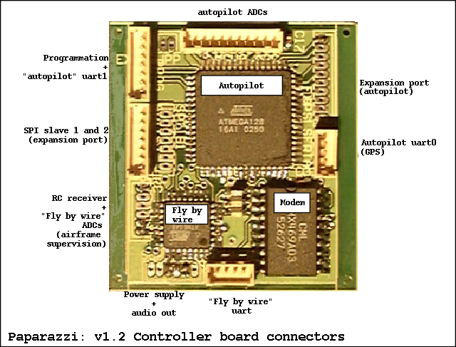
- v1.2.0 connectors
Bottom board
It is the "application board" and is meant to be customized. The example board in the repository has :
- One 1A/5V switching power supply suitable to drive the controller, the camera, the rc receiver and the video transmitter.
- One 10 channel servo driver (4017 decade counter). We have wired only eight connectors.
- One linear hall sensor for motors current monitoring
Radio control receiver
The RF section of a RC receiver can be tricky to build and tune. We use a commercial unit. We tap the output of the hf section to the Paparazzi controller board.
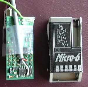
- ACT micro-6
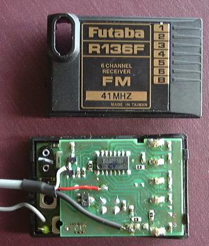
- Futaba R136


We could also use the servo driver but for now we don't need it. Our application board already has one.