At this point, you should have the GNU tools configured, built, and installed on your system. In this chapter, we present a simple example of using the GNU tools in an AVR project. After reading this chapter, you should have a better feel as to how the tools are used and how a Makefile can be configured.
The Project
This project will use the pulse-width modulator (PWM) to ramp an LED on and off every two seconds. An AT90S2313 processor will be used as the controller. The circuit for this demonstration is shown in the schematic diagram. If you have a development kit, you should be able to use it, rather than build the circuit, for this project.
- Note
- Meanwhile, the AT90S2313 became obsolete. Either use its successor, the (pin-compatible) ATtiny2313 for the project, or perhaps the ATmega8 or one of its successors (ATmega48/88/168) which have become quite popular since the original demo project had been established. For all these more modern devices, it is no longer necessary to use an external crystal for clocking as they ship with the internal 1 MHz oscillator enabled, so C1, C2, and Q1 can be omitted. Normally, for this experiment, the external circuitry on /RESET (R1, C3) can be omitted as well, leaving only the AVR, the LED, the bypass capacitor C4, and perhaps R2. For the ATmega8/48/88/168, use PB1 (pin 15 at the DIP-28 package) to connect the LED to. Additionally, this demo has been ported to many different other AVRs. The location of the respective OC pin varies between different AVRs, and it is mandated by the AVR hardware.
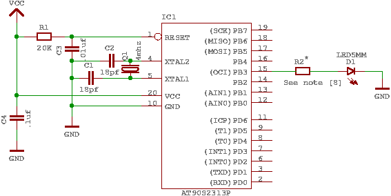
Schematic of circuit for demo project
The source code is given in demo.c. For the sake of this example, create a file called demo.c containing this source code. Some of the more important parts of the code are:
- Note [1]:
- As the AVR microcontroller series has been developed during the past years, new features have been added over time. Even though the basic concepts of the timer/counter1 are still the same as they used to be back in early 2001 when this simple demo was written initially, the names of registers and bits have been changed slightly to reflect the new features. Also, the port and pin mapping of the output compare match 1A (or 1 for older devices) pin which is used to control the LED varies between different AVRs. The file
iocompat.h tries to abstract between all this differences using some preprocessor #ifdef statements, so the actual program itself can operate on a common set of symbolic names. The macros defined by that file are:
OCR the name of the OCR register used to control the PWM (usually either OCR1 or OCR1A)DDROC the name of the DDR (data direction register) for the OC outputOC1 the pin number of the OC1[A] output within its portTIMER1_TOP the TOP value of the timer used for the PWM (1023 for 10-bit PWMs, 255 for devices that can only handle an 8-bit PWM)TIMER1_PWM_INIT the initialization bits to be set into control register 1A in order to setup 10-bit (or 8-bit) phase and frequency correct PWM modeTIMER1_CLOCKSOURCE the clock bits to set in the respective control register to start the PWM timer; usually the timer runs at full CPU clock for 10-bit PWMs, while it runs on a prescaled clock for 8-bit PWMs
- Note [2]:
- ISR() is a macro that marks the function as an interrupt routine. In this case, the function will get called when timer 1 overflows. Setting up interrupts is explained in greater detail in <avr/interrupt.h>: Interrupts.
- Note [3]:
- The
PWM is being used in 10-bit mode, so we need a 16-bit variable to remember the current value.
- Note [4]:
- This section determines the new value of the
PWM.
- Note [5]:
- Here's where the newly computed value is loaded into the
PWM register. Since we are in an interrupt routine, it is safe to use a 16-bit assignment to the register. Outside of an interrupt, the assignment should only be performed with interrupts disabled if there's a chance that an interrupt routine could also access this register (or another register that uses TEMP), see the appropriate FAQ entry.
- Note [6]:
- This routine gets called after a reset. It initializes the
PWM and enables interrupts.
- Note [7]:
- The main loop of the program does nothing – all the work is done by the interrupt routine! The
sleep_mode() puts the processor on sleep until the next interrupt, to conserve power. Of course, that probably won't be noticable as we are still driving a LED, it is merely mentioned here to demonstrate the basic principle.
- Note [8]:
- Early AVR devices saturate their outputs at rather low currents when sourcing current, so the LED can be connected directly, the resulting current through the LED will be about 15 mA. For modern parts (at least for the ATmega 128), however Atmel has drastically increased the IO source capability, so when operating at 5 V Vcc, R2 is needed. Its value should be about 150 Ohms. When operating the circuit at 3 V, it can still be omitted though.
The Source Code
#include "iocompat.h"
enum { UP, DOWN };
{
switch (direction)
{
case UP:
if (++pwm == TIMER1_TOP)
direction = DOWN;
break;
case DOWN:
if (--pwm == 0)
direction = UP;
break;
}
OCR = pwm;
}
void
ioinit (void)
{
TCCR1A = TIMER1_PWM_INIT;
TCCR1B |= TIMER1_CLOCKSOURCE;
#if defined(TIMER1_SETUP_HOOK)
TIMER1_SETUP_HOOK();
#endif
OCR = 0;
}
int
main (void)
{
ioinit ();
for (;;)
return (0);
}
Compiling and Linking
This first thing that needs to be done is compile the source. When compiling, the compiler needs to know the processor type so the -mmcu option is specified. The -Os option will tell the compiler to optimize the code for efficient space usage (at the possible expense of code execution speed). The -g is used to embed debug info. The debug info is useful for disassemblies and doesn't end up in the -c tells the compiler to compile and stop – don't link. This demo is small enough that we could compile and link in one step. However, real-world projects will have several modules and will typically need to break up the building of the project into several compiles and one link.
$ avr-gcc -g -Os -mmcu=atmega8 -c demo.c
The compilation will create a demo.o file. Next we link it into a binary called demo.elf.
$ avr-gcc -g -mmcu=atmega8 -o demo.elf demo.o
It is important to specify the MCU type when linking. The compiler uses the -mmcu option to choose start-up files and run-time libraries that get linked together. If this option isn't specified, the compiler defaults to the 8515 processor environment, which is most certainly what you didn't want.
Examining the Object File
Now we have a binary file. Can we do anything useful with it (besides put it into the processor?) The GNU Binutils suite is made up of many useful tools for manipulating object files that get generated. One tool is avr-objdump, which takes information from the object file and displays it in many useful ways. Typing the command by itself will cause it to list out its options.
For instance, to get a feel of the application's size, the -h option can be used. The output of this option shows how much space is used in each of the sections (the
An even more useful option is -S. This option disassembles the binary file and intersperses the source code in the output! This method is much better, in my opinion, than using the -S with the compiler because this listing includes routines from the libraries and the vector table contents. Also, all the "fix-ups" have been satisfied. In other words, the listing generated by this option reflects the actual code that the processor will run.
$ avr-objdump -h -S demo.elf > demo.lst
Here's the output as saved in the demo.lst file:
demo.elf:     file format elf32-avr

Sections:
Idx Name          Size      VMA       LMA       File off  Algn
  0 .text         000000d8  00000000  00000000  00000094  2**1
                  CONTENTS, ALLOC, LOAD, READONLY, CODE
  1 .data         00000000  00800060  000000d8  0000016c  2**0
                  CONTENTS, ALLOC, LOAD, DATA
  2 .bss          00000003  00800060  00800060  0000016c  2**0
                  ALLOC
  3 .stab         00000354  00000000  00000000  0000016c  2**2
                  CONTENTS, READONLY, DEBUGGING
  4 .stabstr      000001ce  00000000  00000000  000004c0  2**0
                  CONTENTS, READONLY, DEBUGGING
  5 .comment      00000012  00000000  00000000  0000068e  2**0
                  CONTENTS, READONLY
  6 .note.gnu.avr.deviceinfo 0000003c  00000000  00000000  000006a0  2**2
                  CONTENTS, READONLY
  7 .debug_info   0000048c  00000000  00000000  000006dc  2**0
                  CONTENTS, READONLY, DEBUGGING
  8 .debug_abbrev 0000044e  00000000  00000000  00000b68  2**0
                  CONTENTS, READONLY, DEBUGGING
  9 .debug_line   0000001d  00000000  00000000  00000fb6  2**0
                  CONTENTS, READONLY, DEBUGGING
 10 .debug_str    0000017a  00000000  00000000  00000fd3  2**0
                  CONTENTS, READONLY, DEBUGGING

Disassembly of section .text:

00000000 <__vectors>:
   0:	12 c0       	rjmp	.+36     	; 0x26 <__ctors_end>
   2:	21 c0       	rjmp	.+66     	; 0x46 <__bad_interrupt>
   4:	20 c0       	rjmp	.+64     	; 0x46 <__bad_interrupt>
   6:	1f c0       	rjmp	.+62     	; 0x46 <__bad_interrupt>
   8:	1e c0       	rjmp	.+60     	; 0x46 <__bad_interrupt>
   a:	1d c0       	rjmp	.+58     	; 0x46 <__bad_interrupt>
   c:	1c c0       	rjmp	.+56     	; 0x46 <__bad_interrupt>
   e:	1b c0       	rjmp	.+54     	; 0x46 <__bad_interrupt>
  10:	1b c0       	rjmp	.+54     	; 0x48 <__vector_8>
  12:	19 c0       	rjmp	.+50     	; 0x46 <__bad_interrupt>
  14:	18 c0       	rjmp	.+48     	; 0x46 <__bad_interrupt>
  16:	17 c0       	rjmp	.+46     	; 0x46 <__bad_interrupt>
  18:	16 c0       	rjmp	.+44     	; 0x46 <__bad_interrupt>
  1a:	15 c0       	rjmp	.+42     	; 0x46 <__bad_interrupt>
  1c:	14 c0       	rjmp	.+40     	; 0x46 <__bad_interrupt>
  1e:	13 c0       	rjmp	.+38     	; 0x46 <__bad_interrupt>
  20:	12 c0       	rjmp	.+36     	; 0x46 <__bad_interrupt>
  22:	11 c0       	rjmp	.+34     	; 0x46 <__bad_interrupt>
  24:	10 c0       	rjmp	.+32     	; 0x46 <__bad_interrupt>

00000026 <__ctors_end>:
  26:	11 24       	eor	r1, r1
  28:	1f be       	out	0x3f, r1	; 63
  2a:	cf e5       	ldi	r28, 0x5F	; 95
  2c:	d4 e0       	ldi	r29, 0x04	; 4
  2e:	de bf       	out	0x3e, r29	; 62
  30:	cd bf       	out	0x3d, r28	; 61

00000032 <__do_clear_bss>:
  32:	20 e0       	ldi	r18, 0x00	; 0
  34:	a0 e6       	ldi	r26, 0x60	; 96
  36:	b0 e0       	ldi	r27, 0x00	; 0
  38:	01 c0       	rjmp	.+2      	; 0x3c <.do_clear_bss_start>

0000003a <.do_clear_bss_loop>:
  3a:	1d 92       	st	X+, r1

0000003c <.do_clear_bss_start>:
  3c:	a3 36       	cpi	r26, 0x63	; 99
  3e:	b2 07       	cpc	r27, r18
  40:	e1 f7       	brne	.-8      	; 0x3a <.do_clear_bss_loop>
  42:	3f d0       	rcall	.+126    	; 0xc2 <main>
  44:	47 c0       	rjmp	.+142    	; 0xd4 <_exit>

00000046 <__bad_interrupt>:
  46:	dc cf       	rjmp	.-72     	; 0x0 <__vectors>

00000048 <__vector_8>:
#include "iocompat.h"		/* Note [1] */

enum { UP, DOWN };

ISR (TIMER1_OVF_vect)		/* Note [2] */
{
  48:	1f 92       	push	r1
  4a:	1f b6       	in	r1, 0x3f	; 63
  4c:	1f 92       	push	r1
  4e:	11 24       	eor	r1, r1
  50:	2f 93       	push	r18
  52:	8f 93       	push	r24
  54:	9f 93       	push	r25
    static uint16_t pwm;	/* Note [3] */
    static uint8_t direction;

    switch (direction)		/* Note [4] */
  56:	20 91 62 00 	lds	r18, 0x0062	; 0x800062 <direction.1>
    {
        case UP:
            if (++pwm == TIMER1_TOP)
  5a:	80 91 60 00 	lds	r24, 0x0060	; 0x800060 <_edata>
  5e:	90 91 61 00 	lds	r25, 0x0061	; 0x800061 <_edata+0x1>
    switch (direction)		/* Note [4] */
  62:	22 23       	and	r18, r18
  64:	a1 f0       	breq	.+40     	; 0x8e <__vector_8+0x46>
  66:	21 30       	cpi	r18, 0x01	; 1
  68:	49 f4       	brne	.+18     	; 0x7c <__vector_8+0x34>
                direction = DOWN;
            break;

        case DOWN:
            if (--pwm == 0)
  6a:	01 97       	sbiw	r24, 0x01	; 1
  6c:	90 93 61 00 	sts	0x0061, r25	; 0x800061 <_edata+0x1>
  70:	80 93 60 00 	sts	0x0060, r24	; 0x800060 <_edata>
  74:	00 97       	sbiw	r24, 0x00	; 0
  76:	11 f4       	brne	.+4      	; 0x7c <__vector_8+0x34>
                direction = UP;
  78:	10 92 62 00 	sts	0x0062, r1	; 0x800062 <direction.1>
            break;
    }

    OCR = pwm;			/* Note [5] */
  7c:	9b bd       	out	0x2b, r25	; 43
  7e:	8a bd       	out	0x2a, r24	; 42
}
  80:	9f 91       	pop	r25
  82:	8f 91       	pop	r24
  84:	2f 91       	pop	r18
  86:	1f 90       	pop	r1
  88:	1f be       	out	0x3f, r1	; 63
  8a:	1f 90       	pop	r1
  8c:	18 95       	reti
            if (++pwm == TIMER1_TOP)
  8e:	01 96       	adiw	r24, 0x01	; 1
  90:	90 93 61 00 	sts	0x0061, r25	; 0x800061 <_edata+0x1>
  94:	80 93 60 00 	sts	0x0060, r24	; 0x800060 <_edata>
  98:	8f 3f       	cpi	r24, 0xFF	; 255
  9a:	23 e0       	ldi	r18, 0x03	; 3
  9c:	92 07       	cpc	r25, r18
  9e:	71 f7       	brne	.-36     	; 0x7c <__vector_8+0x34>
                direction = DOWN;
  a0:	21 e0       	ldi	r18, 0x01	; 1
  a2:	20 93 62 00 	sts	0x0062, r18	; 0x800062 <direction.1>
  a6:	ea cf       	rjmp	.-44     	; 0x7c <__vector_8+0x34>

000000a8 <ioinit>:

void
ioinit (void)			/* Note [6] */
{
    /* Timer 1 is 10-bit PWM (8-bit PWM on some ATtinys). */
    TCCR1A = TIMER1_PWM_INIT;
  a8:	83 e8       	ldi	r24, 0x83	; 131
  aa:	8f bd       	out	0x2f, r24	; 47
     * Start timer 1.
     *
     * NB: TCCR1A and TCCR1B could actually be the same register, so
     * take care to not clobber it.
     */
    TCCR1B |= TIMER1_CLOCKSOURCE;
  ac:	8e b5       	in	r24, 0x2e	; 46
  ae:	81 60       	ori	r24, 0x01	; 1
  b0:	8e bd       	out	0x2e, r24	; 46
#if defined(TIMER1_SETUP_HOOK)
    TIMER1_SETUP_HOOK();
#endif

    /* Set PWM value to 0. */
    OCR = 0;
  b2:	1b bc       	out	0x2b, r1	; 43
  b4:	1a bc       	out	0x2a, r1	; 42

    /* Enable OC1 as output. */
    DDROC = _BV (OC1);
  b6:	82 e0       	ldi	r24, 0x02	; 2
  b8:	87 bb       	out	0x17, r24	; 23

    /* Enable timer 1 overflow interrupt. */
    TIMSK = _BV (TOIE1);
  ba:	84 e0       	ldi	r24, 0x04	; 4
  bc:	89 bf       	out	0x39, r24	; 57
    sei ();
  be:	78 94       	sei
}
  c0:	08 95       	ret

000000c2 <main>:

int
main (void)
{

    ioinit ();
  c2:	f2 df       	rcall	.-28     	; 0xa8 <ioinit>

    /* loop forever, the interrupts are doing the rest */

    for (;;)			/* Note [7] */
        sleep_mode();
  c4:	85 b7       	in	r24, 0x35	; 53
  c6:	80 68       	ori	r24, 0x80	; 128
  c8:	85 bf       	out	0x35, r24	; 53
  ca:	88 95       	sleep
  cc:	85 b7       	in	r24, 0x35	; 53
  ce:	8f 77       	andi	r24, 0x7F	; 127
  d0:	85 bf       	out	0x35, r24	; 53
  d2:	f8 cf       	rjmp	.-16     	; 0xc4 <main+0x2>

000000d4 <_exit>:
  d4:	f8 94       	cli

000000d6 <__stop_program>:
  d6:	ff cf       	rjmp	.-2      	; 0xd6 <__stop_program>
Linker Map Files
avr-objdump is very useful, but sometimes it's necessary to see information about the link that can only be generated by the linker. A map file contains this information. A map file is useful for monitoring the sizes of your code and data. It also shows where modules are loaded and which modules were loaded from libraries. It is yet another view of your application. To get a map file, I usually add -Wl,-Map,demo.map to my link command. Relink the application using the following command to generate demo.map (a portion of which is shown below).
$ avr-gcc -g -mmcu=atmega8 -Wl,-Map,demo.map -o demo.elf demo.o
Some points of interest in the demo.map file are:
.rela.plt
*(.rela.plt)
.text 0x0000000000000000 0xd8
*(.vectors)
.vectors 0x0000000000000000 0x26 /usr/local/lib/gcc/avr/10.2.0/../../../../avr/lib/avr4/crtatmega8.o
0x0000000000000000 __vectors
0x0000000000000000 __vector_default
*(.vectors)
*(.progmem.gcc*)
0x0000000000000026 . = ALIGN (0x2)
0x0000000000000026 __trampolines_start = .
*(.trampolines)
.trampolines 0x0000000000000026 0x0 linker stubs
*(.trampolines*)
0x0000000000000026 __trampolines_end = .
*libprintf_flt.a:*(.progmem.data)
*libc.a:*(.progmem.data)
*(.progmem.*)
0x0000000000000026 . = ALIGN (0x2)
*(.lowtext)
*(.lowtext*)
0x0000000000000026 __ctors_start = .
The
*(.fini2)
*(.fini2)
*(.fini1)
*(.fini1)
*(.fini0)
.fini0 0x00000000000000d4 0x4 /usr/local/lib/gcc/avr/10.2.0/avr4/libgcc.a(_exit.o)
*(.fini0)
*(.hightext)
*(.hightext*)
*(.progmemx.*)
0x00000000000000d8 . = ALIGN (0x2)
*(.jumptables)
*(.jumptables*)
0x00000000000000d8 _etext = .
.data 0x0000000000800060 0x0 load address 0x00000000000000d8
[!provide] PROVIDE (__data_start = .)
*(.data)
.data 0x0000000000800060 0x0 /usr/local/lib/gcc/avr/10.2.0/../../../../avr/lib/avr4/crtatmega8.o
.data 0x0000000000800060 0x0 demo.o
.data 0x0000000000800060 0x0 /usr/local/lib/gcc/avr/10.2.0/avr4/libgcc.a(_exit.o)
.data 0x0000000000800060 0x0 /usr/local/lib/gcc/avr/10.2.0/avr4/libgcc.a(_clear_bss.o)
*(.data*)
*(.gnu.linkonce.d*)
*(.rodata)
*(.rodata*)
*(.gnu.linkonce.r*)
0x0000000000800060 . = ALIGN (0x2)
0x0000000000800060 _edata = .
[!provide] PROVIDE (__data_end = .)
.bss 0x0000000000800060 0x3
0x0000000000800060 PROVIDE (__bss_start = .)
*(.bss)
.bss 0x0000000000800060 0x0 /usr/local/lib/gcc/avr/10.2.0/../../../../avr/lib/avr4/crtatmega8.o
.bss 0x0000000000800060 0x3 demo.o
.bss 0x0000000000800063 0x0 /usr/local/lib/gcc/avr/10.2.0/avr4/libgcc.a(_exit.o)
.bss 0x0000000000800063 0x0 /usr/local/lib/gcc/avr/10.2.0/avr4/libgcc.a(_clear_bss.o)
*(.bss*)
*(COMMON)
0x0000000000800063 PROVIDE (__bss_end = .)
0x00000000000000d8 __data_load_start = LOADADDR (.data)
0x00000000000000d8 __data_load_end = (__data_load_start + SIZEOF (.data))
.noinit 0x0000000000800063 0x0
[!provide] PROVIDE (__noinit_start = .)
*(.noinit*)
[!provide] PROVIDE (__noinit_end = .)
0x0000000000800063 _end = .
[!provide] PROVIDE (__heap_start = .)
.eeprom 0x0000000000810000 0x0
*(.eeprom*)
0x0000000000810000 __eeprom_end = .
The last address in the 0x114 ( denoted by _etext ), so the instructions use up 276 bytes of FLASH.
The 0x60, which is the first address after the register bank on an ATmega8 processor.
The next available address in the 0x60, so the application has no initialized data.
The 0x60.
The next available address in the
The
The next available address in the
Generating Intel Hex Files
We have a binary of the application, but how do we get it into the processor? Most (if not all) programmers will not accept a GNU executable as an input file, so we need to do a little more processing. The next step is to extract portions of the binary and save the information into avr-objcopy.
The ROM contents can be pulled from our project's binary and put into the file demo.hex using the following command:
$ avr-objcopy -j .text -j .data -O ihex demo.elf demo.hex
The resulting demo.hex file contains:
:1000000012C021C020C01FC01EC01DC01CC01BC00C
:100010001BC019C018C017C016C015C014C013C02B
:1000200012C011C010C011241FBECFE5D4E0DEBF46
:10003000CDBF20E0A0E6B0E001C01D92A336B2071C
:10004000E1F73FD047C0DCCF1F921FB61F921124AB
:100050002F938F939F9320916200809160009091E5
:1000600061002223A1F0213049F4019790936100AF
:1000700080936000009711F4109262009BBD8ABDCE
:100080009F918F912F911F901FBE1F9018950196E1
:1000900090936100809360008F3F23E0920771F797
:1000A00021E020936200EACF83E88FBD8EB58160A6
:1000B0008EBD1BBC1ABC82E087BB84E089BF7894EC
:1000C0000895F2DF85B7806885BF889585B78F77FB
:0800D00085BFF8CFF894FFCFC3
:00000001FF
The -j option indicates that we want the information from the
$ avr-objcopy -j .eeprom --change-section-lma .eeprom=0 -O ihex demo.elf demo_eeprom.hex
There is no demo_eeprom.hex file written, as that file would be empty.
Starting with version 2.17 of the GNU binutils, the avr-objcopy command that used to generate the empty EEPROM files now aborts because of the empty input section
Letting Make Build the Project
Rather than type these commands over and over, they can all be placed in a make file. To build the demo project using make, save the following in a file called Makefile.
- Note
- This
Makefile can only be used as input for the GNU version of make.
PRG = demo
OBJ = demo.o
#MCU_TARGET = at90s2313
#MCU_TARGET = at90s2333
#MCU_TARGET = at90s4414
#MCU_TARGET = at90s4433
#MCU_TARGET = at90s4434
#MCU_TARGET = at90s8515
#MCU_TARGET = at90s8535
#MCU_TARGET = atmega128
#MCU_TARGET = atmega1280
#MCU_TARGET = atmega1281
#MCU_TARGET = atmega1284p
#MCU_TARGET = atmega16
#MCU_TARGET = atmega163
#MCU_TARGET = atmega164p
#MCU_TARGET = atmega165
#MCU_TARGET = atmega165p
#MCU_TARGET = atmega168
#MCU_TARGET = atmega169
#MCU_TARGET = atmega169p
#MCU_TARGET = atmega2560
#MCU_TARGET = atmega2561
#MCU_TARGET = atmega32
#MCU_TARGET = atmega324p
#MCU_TARGET = atmega325
#MCU_TARGET = atmega3250
#MCU_TARGET = atmega329
#MCU_TARGET = atmega3290
#MCU_TARGET = atmega32u4
#MCU_TARGET = atmega48
#MCU_TARGET = atmega64
#MCU_TARGET = atmega640
#MCU_TARGET = atmega644
#MCU_TARGET = atmega644p
#MCU_TARGET = atmega645
#MCU_TARGET = atmega6450
#MCU_TARGET = atmega649
#MCU_TARGET = atmega6490
MCU_TARGET = atmega8
#MCU_TARGET = atmega8515
#MCU_TARGET = atmega8535
#MCU_TARGET = atmega88
#MCU_TARGET = attiny2313
#MCU_TARGET = attiny24
#MCU_TARGET = attiny25
#MCU_TARGET = attiny26
#MCU_TARGET = attiny261
#MCU_TARGET = attiny44
#MCU_TARGET = attiny45
#MCU_TARGET = attiny461
#MCU_TARGET = attiny84
#MCU_TARGET = attiny85
#MCU_TARGET = attiny861
OPTIMIZE = -O2
DEFS =
LIBS =
# You should not have to change anything below here.
CC = avr-gcc
# Override is only needed by avr-lib build system.
override CFLAGS = -g -Wall $(OPTIMIZE) -mmcu=$(MCU_TARGET) $(DEFS)
override LDFLAGS = -Wl,-Map,$(PRG).map
OBJCOPY = avr-objcopy
OBJDUMP = avr-objdump
all: $(PRG).elf lst text eeprom
$(PRG).elf: $(OBJ)
$(CC) $(CFLAGS) $(LDFLAGS) -o $@ $^ $(LIBS)
# dependency:
demo.o: demo.c iocompat.h
clean:
rm -rf *.o $(PRG).elf *.eps *.png *.pdf *.bak
rm -rf *.lst *.map $(EXTRA_CLEAN_FILES)
lst: $(PRG).lst
%.lst: %.elf
$(OBJDUMP) -h -S $< > $@
# Rules for building the .text rom images
text: hex bin srec
hex: $(PRG).hex
bin: $(PRG).bin
srec: $(PRG).srec
%.hex: %.elf
$(OBJCOPY) -j .text -j .data -O ihex $< $@
%.srec: %.elf
$(OBJCOPY) -j .text -j .data -O srec $< $@
%.bin: %.elf
$(OBJCOPY) -j .text -j .data -O binary $< $@
# Rules for building the .eeprom rom images
eeprom: ehex ebin esrec
ehex: $(PRG)_eeprom.hex
ebin: $(PRG)_eeprom.bin
esrec: $(PRG)_eeprom.srec
%_eeprom.hex: %.elf
$(OBJCOPY) -j .eeprom --change-section-lma .eeprom=0 -O ihex $< $@ \
|| { echo empty $@ not generated; exit 0; }
%_eeprom.srec: %.elf
$(OBJCOPY) -j .eeprom --change-section-lma .eeprom=0 -O srec $< $@ \
|| { echo empty $@ not generated; exit 0; }
%_eeprom.bin: %.elf
$(OBJCOPY) -j .eeprom --change-section-lma .eeprom=0 -O binary $< $@ \
|| { echo empty $@ not generated; exit 0; }
# Every thing below here is used by avr-libc's build system and can be ignored
# by the casual user.
FIG2DEV = fig2dev
EXTRA_CLEAN_FILES = *.hex *.bin *.srec
dox: eps png pdf
eps: $(PRG).eps
png: $(PRG).png
pdf: $(PRG).pdf
%.eps: %.fig
$(FIG2DEV) -L eps $< $@
%.pdf: %.fig
$(FIG2DEV) -L pdf $< $@
%.png: %.fig
$(FIG2DEV) -L png $< $@
Reference to the source code