Summary
The goal of OpenPanorama is to give to the panoramic imaging world a complete and free to use file format based on XML.
We also believe that it is important to be able to convert other proprietary file formats to OpenPanorama without loss of data or image quality (no change of projection type or recompression of the image).
This document provides a summary of the different types of panoramas and their functionality , all of which will be supported by the OpenPanorama format.
In this document we assume you are familiar with panoramic photography. For more information about panoramic imaging, see James Rigg's web site http://www.panoguide.com
Panoramas are composed of :
- one or more
pictures with their associated projection
- hotspots
- sounds
- light effects
- data such as GPS co-ordinates, north, entry point
- scripting language
- hotspots
- sounds
- light effects
- data such as GPS co-ordinates, north, entry point
- scripting language
| I. Projections |
There are four projections in general use today:
- cylindrical
- spherical
- cubic
- flat
- spherical
- cubic
- flat
A.
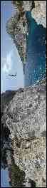
Cylindrical projection
Cylindrical projection provides a 360 degree
panoramic view but is limited in the vertical axis - some of the sky or
ceiling and of the floor or ground is omitted.To display a cylindrical image, it is projected onto a cylinder. The image is then viewed from the center of the cylinder. The source image is mapped on the cylinder using a gnomonic projection identical to gnomonic projections used to create earth maps.
 |
+ |
 |
= |
 |
The source image can be horizontal or vertical and in certain cases be segmented:
 |
 |
 |
Today, many different solutions exist for storing cylindrical images. OpenPanorama's image description syntax is flexible enough to accomodate all existing image formats in the context of panoramic imaging. See “Image Format part”, below.
Attributes of a cylindrical panorama:
Because the panorama can be a partial view of the scene (less than 360 degrees), it is important to be able to specify the horizontal field of view (without which the image cannot be displayed correctly). The vertical field of view is deduced automatically from the relationship between the height and the width of the image.
Points in the panoramic scene can be described in terms of their horizontal and vertical angles within the cylinder. For example, to define 'north' in the image compared to the north of other objects in the panorama.
B.
Spherical projection
Spherical projection involves mapping the image of
the environment on a sphere. Unlike cylindrical images, spherical images
provide a complete representation of the environment - i.e. including
the ground below the camera and the sky. However, it is also possible to
use this system for panorama whose vertical field is lower than
180° with specifying a max/min vertical tilt. The source image can be of various types, but the most commonly used is that that requires equirectangular projection. For a panorama of 360°x180°, the image has a constant aspect ratio of 2:1 (exactly twice as wide as it is high).
 |
+ |  |
= |  |
This system is used a lot by people who use PTViewer to display their panoramas. The images used with PTViewer are generally stored in only one image file, as represented in the example above.
Attributes of the spherical panorama:
Because the panorama can be a partial view of the scene (less than 360 degrees) , it is important to be able to specify the horizontal field of view (without which the image cannot be displayed correctly). The vertical field of view is deduced automatically from the relationship between the height and the width of the image.
Points in the panoramic scene can be described in terms of their horizontal and vertical angles within the sphere. For example, to define 'north' in the image compared to the north of other objects in the panorama.
C.
Cubic projection
Very
popular since QuickTime® 5, cubic projection consists of projecting
the environment on a cube, and positioning the viewpoint in the centre.
The visualization software’s projection algorithm corrects the
perspectives of the 6 cube faces and gives the impression that the user
is in a spherical view. |
+ |
 |
= |
 |
The six faces of the cube can be stored in various ways:
- vertically in only one file (the
order of the faces may vary)
- horizontally in only one file (the order of the faces may vary)
- in groups of 2 or 3, horizontally or vertically (the order of the faces may vary)
- in six different image files
- each cube face segmented or “tiled” into smaller images (4,9,16 or more)
- horizontally in only one file (the order of the faces may vary)
- in groups of 2 or 3, horizontally or vertically (the order of the faces may vary)
- in six different image files
- each cube face segmented or “tiled” into smaller images (4,9,16 or more)
The OpenPanorama image description syntax is flexible enough to accommodate all existing image formats in the context of panoramic imaging. See “Image Format part”, below.
Attributes of the cubic panorama:
Because the panorama can be a partial view of the scene (less than 360 or 180 degrees) , it is important to be able to specify the horizontal and vertical field of view.
Points in the panoramic scene can be described in terms of their horizontal and vertical angles within the cube. For example, to define 'north' in the image compared to the north of other objects in the panorama.
D.
Flat projection
Flat projection consists in placing a planar image in the panoramic environment. (Note that a cubic panorama is made up of 6 flat projections.)
Flat projection does not provide a useful means of displaying a full panoramic image, but is very useful for adding images to the panoramic scene, or for certain types of hotspots, as we will see later.
Note that “flat” or “planar” projection is sometimes used to describe how some software displays panoramic images without projecting the image at all – i.e. providing a non-perspectively correct view of a panoramic image.

Attributes of a flat projection:
We consider that the diagonals of the image are perpendicular to the line passing by the intersection of the diagonals and the point of visualization.
To position the mapped image in our panoramic environment, we need:
- two angles giving the angular
position of the centre of the image (horizontal and vertical angle)
- a horizontal field of view of the image (the aperture) which makes it possible to know the distance of the image
- a swing angle making it possible to turn the image around the axis passing by the point of crossing of the diagonals and the point of view.
- a horizontal field of view of the image (the aperture) which makes it possible to know the distance of the image
- a swing angle making it possible to turn the image around the axis passing by the point of crossing of the diagonals and the point of view.
E.
Comparison of the mappings of various projections
Cylindrical
projection:(360°x100°)

Spherical Projection:(360°x180°)
Cubic projection:(360°x180°)

Flat projection:(90°x68°)
Spherical Projection:(360°x180°)
Cubic projection:(360°x180°)
Flat projection:(90°x68°)

| II. Hotspots |
Currently, three major types of hotspots exist:
- hotspots defined using masks
- hotspots defined by a 3D rectangle
- the hotspots defined by a point or a surface of fixed size in the viewer interface (outside of the mapped environment)
- hotspots defined by a 3D rectangle
- the hotspots defined by a point or a surface of fixed size in the viewer interface (outside of the mapped environment)
A. Hotspots using mask
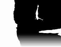
To define hostpots using a mask, a mask image the same size as the panoramic image contains blocks of colour that correspond to each clickable zone (hotspot) within the panoramic scene. Each colour corresponds to a different hotspot.
These masks use the same type of projection as the image(s) for which they define hotspots.
This approach is very flexible in that a hotspot can be any shape. However manually defining hotspots in this way is time consuming – ideally software tools automate the process.
Here is an example:
Image of the
panorama:
Obtained hotspot:
Corresponding mask:
 |
Obtained hotspot:

B.
Hotspots defined by a 3D rectangle
The following diagrams show a hotspot defined by a 3D rectangle (illustrated by the translucent blue rectangle).
The size of this hotspot is defined by the angles γ and ε.
It is positioned in 3d thanks to the two angles α and β.
It is possible to turn this rectangle around axis OC. (This angle is not shown on the diagrams in order to keep them simple. In the following example, this angle is considered to be null.)

Advantages:
- more
precise than ‘point’ hotspots (see below)
- smaller file size than when using hotspot masks
- faster to implement than the mask hotspot
- smaller file size than when using hotspot masks
- faster to implement than the mask hotspot
Disadvantages:
- the
active zone is less precise than when using masks
- the shape of the hotspot is always a rectangle (a mask permits any shape hotspot)
- the shape of the hotspot is always a rectangle (a mask permits any shape hotspot)
C.
Point hotspots
A
hotspot can be defined on appoint using just two angles (α and β).
The sensitivity of the hotspot (i.e.how close the
user must click to this point in order to activate the hotspot) is
defined by the viewer.
Advantages:
- very easy to use (only two parameters)
- optimal file size (definition requires just two parameters)
- optimal file size (definition requires just two parameters)
Disadvantages:
- the surface of the active zone around
the point is arbitrary
- the size of the active zone does not vary when zooming or unzooming
- the size of the active zone does not vary when zooming or unzooming
| III. Sounds |
Sounds are not often used in panoramas or virtual tours. However, they can make the panorama come to life.
Two types of sound can be defined:
- 2D sounds
- 3D sounds
- 3D sounds
A. 2D sounds
2D sounds are generally used to give a global
environment to the panorama.They require only few parameters:
- the sound file
- volume
- to play once or loop
- whether to play as soon as the panorama loads, or not
- volume
- to play once or loop
- whether to play as soon as the panorama loads, or not
Volume is not used here to control the total volume of the sounds in the panoramic scene, but to control the relative volume of different sounds
B.
3D sounds
Spacial
sounds are used even less than 2D sounds in panoramic imaging, but they
can make a panorama seem even more ‘alive’ in that they appear to
interact with the user. The parameters used are exactly the same as those for 2D sound, but with two more angles (α and β) which make it possible to position the sound in 3D. (see diagram).

| IV.
Light effects |
Light effects were introduced by ImmerVision. Like 3D sounds, they make it possible to make panoramas more dynamic, and add a feeling of reality by simulating the effects of real light sources. The user gets the impression of looking around a non-static environment.
A light is positioned simply using two angles (α and β), as shown on the following diagram:

There are two types of light effects, which can be used simultaneously:
- dazzle or glare
- lens flare
- lens flare
A.
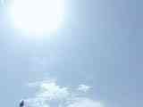
Dazzle
Dazzle
simulates the effect we perceive have when we look at the sun with the
naked eye or with a camera and are momentarily “blinded” by the
intensity of the light.Without dazzle:
With dazzle:
With dazzle:
B.
Lens flare
Lens
flare is the aureoles, which appear when a multiple-element optical
system has a source of intense light in its field.Without lens flare:
With lens flare:

With lens flare:
This
effect is obtained with using an image that defines the series of
optical artefacts that simulate the refraction of light within a
lens. The image below is an example:

This means that a user can easily define his or her own lens flare using some very simple parameters.
| V.
Other useful data |
Various useful information can be added to the panorama such as:
- copyright
- description
- GPS co-ordinates
- north direction
- default entry point
- limits of movement
- description
- GPS co-ordinates
- north direction
- default entry point
- limits of movement
A.
Copyright
In the majority of panoramic file formats there is no means of
specifying copyright ownership or licence terms. However, this
information is important, because it makes it possible for the author to
assert ownership and the terms for the use and the redistribution of the
workB.
Description
Description simply gives more information about the panorama.
This can be a description of the scene, conditions of the shoot,
etc.... C.
GPS
GPS
co-ordinates give the geographical position of the panorama as well as
the date and time when the photos were taken. They can also be used to automatically position a point on a map.
D.
North direction
Although
we mean magnetic north, the north direction can be an arbitrary
direction other than north.By indicating the north direction in each panorama in a virtual tour, it is possible to keep the same direction of view when we pass from one panorama to another (without having to separately specify “leaving” and “entry” points for hotspots). This can also provide a more realistic virtual tour experience for the end user. Moreover, it makes it possible to automatically control the direction of a compass whose role would be to show the direction of view on a map (a good example of this can be seen in Poor Man’s VR (PMVR) at http://www.duckware.com/).
E.
Default entry point
The default point of view is given by the value of the zoom, horizontal
and vertical rotations. It makes it possible to specify the
initial view when the panorama is first loaded. This entry point
is not used when a person uses a hotspots in a virtual visit to pass
from a panorama to another.F.
Movements limits
Movement limits make it possible to limit horizontal and vertical
panning within the viewer as well as the zoom. Limit
on zoom is typically used to prevent the end user zooming in beyond the
actual resolution of the image (which would only result in a pixelated
view).| VI. Scripting language |
Currently, several viewers of panoramic images support basic script languages.
OpenPanorama will support its own simple script language allowing the control of and interaction with the various objects in the panorama. However compatibility with complex languages like AppleScript® used by QuickTime® will not be provided because of their complexity.
| VII. OpenPanorama image format |
Why create an OpenPanorama image format?
There are, at least, two reasons to the use of such an image format:
- to recreate a mapping compatible with
OpenPanorama without having to modify the source images (to
reorganize cubic or cylindrical mappings)
- to add functionalities to the most used image file format..
- to add functionalities to the most used image file format..
A.
Mapping creation
To
better understand the goal of this functionality, let us take again the
cylindrical example of panoramas used by QuickTime®. The original
images are organized as shown below:
Fig 1.
For use in an OpenPanorama panorama, we want the images to be organized in the following form:
Thanks to the OpenPanorama image XML specification it's simple to give the size of the image we want, as well as the way to position each image of figure 1 inside. That is done simply with using source and destination rectangles.
In this way a segmented or “tiled” image can be treated as if it is a single image, without having to modify the original images, or recompress it (Note that the majority of the current systems of compression are lossy, and recompression decreases the quality of the image considerably).
This principle can also be applied to cubic, and even spherical image mappings.
B.
Additional of functionality
Today, the most widely used image formats for panoramas are GIF and JPEG, because they are natively supported by Java. However, these image formats have limited functionality:
- GIF
provides a means of specifying transparency for a single color,
animations, and uses a colour palette of up to256 colors
- JPEG has a 24bit color palette, but does not provide a means of specifying transparency
- JPEG has a 24bit color palette, but does not provide a means of specifying transparency
It should be possible to use these traditional file formats (or others including video formats) to create images with more capabilities.
For example, it is possible to apply a variable transparency to a JPEG image using a simple gray level mask.
We take an image:
The following image is obtained: (red shows transparency)

and apply the following transparency
mask: (white = opaque and black = transparent):
 |
The following image is obtained: (red shows transparency)
This is a simple example of what such a system would allow. Note, it would be possible to optimize the size of the panorama file by compressing the mask more heavily than the panoramic image. (This is because a mask is unlikely to need to be as good quality as the actual panorama.)
We also envisage creating animations using several images, adding a transparency mask to a video, etc....
Copyright (c) 2002-2003
OpenPanorama