The board wiring fits the Atmel radio development kit hardware and compatibles. It uses a FTDI245 chip as Host Interface.
The wiring of the radio and the ATmega is shown below:
     AVR      RF230
     ---      -----
     PB4  -->  SLPTR
     P??  <--  MCLK
     PD4  <--  IRQ (ICP1)
     PB5  -->  RSTN
     PB0  -->  SS
     PB2  -->  MOSI
     PB3  <--  MISO
     PB1  -->  SCK
    The STK541 has no LEDS and Keys, so we define the ressources
    from the  RCB230 here.
    KEY: PE5
    LEDS: PE2:PE4
DBG: PD0 - connector X20:2 (ground X20:1)
Fuses/Locks:
     LF: 0xe2 - 8MHz internal RC Osc.
     HF: 0x11 - without boot loader
     HF: 0x10 - with boot loader
     EF: 0xff
     LOCK: 0xef - protection of boot section
Bootloader:
    Start at byte=0x1e000, address=0xf000, size = 4096 instructions/ 8192 bytes
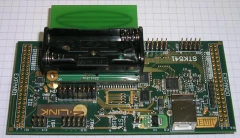
Atmel STK541 and Radio Controller Board
Defines | |
| #define | BOARD_TYPE (STK_541) |
| #define | MAX_FRAME_SIZE (127) |
| #define | TIMER_INIT() |
| #define | TIMER_IRQ_vect TIMER1_OVF_vect |
| #define BOARD_TYPE (STK_541) |
ID String for this hardware
stk541 is an Atmel STK541 equipped with an RCB230 with AT86RF230 Rev.Astk541b is an Atmel STK541 equipped with an RCB230 with AT86RF230 Rev.B | #define MAX_FRAME_SIZE (127) |
maximum allowed frame size
| #define TIMER_INIT | ( | ) |
Value:
do{ \
        TCCR1B |= (_BV(CS10));\
        TIMSK1 |= _BV(TOIE1); \
    }while(0)
Timer is clocked at F_CPU, and TIMER_IRQ_vect is called every 65535 ticks.
| #define TIMER_IRQ_vect TIMER1_OVF_vect |
Vector for Timer IRQ routine
 1.5.5
1.5.5