This short tutorial explains the use of the mockup schematic entry tool of Gossip. The schemtic entry itself, being only a mockup, is not really meant serious but it is useful enough to make it easier to enter the world of Gossip.
The mockup is not very robust, and you should expect some annoying behaviour from time to time. It should be reasonably careful with your files, tho.
When the gossip-ed package has been installed on your system, you
have access to the program gossip-ed-mockup. This is a simple
schematic entry tool for creating hiearchical blocks. You can use these
hiearchical blocks in simulations just like any other blocks.
There are no special files associated with the schematic entry tool, it stores all its extra information (like the graphical representation of the block) in the same file that also contains the code for the block itself. This extra information is ignored during a simulation.
This tutorial will show you how to recreate the Fibonacci number
generator from example 4 of the gossip-sim documentation. It
will be divided into three blocks:
impulse-source
fibonacci block.
fibonacci
testbench
impulse-source, a fibonacci block
and a destination to actually bring the numbers to the screen.
As a first step, start gossip-ed-mockup. We will put new files
in the current directory so make sure that you start the program in a
suitable directory.
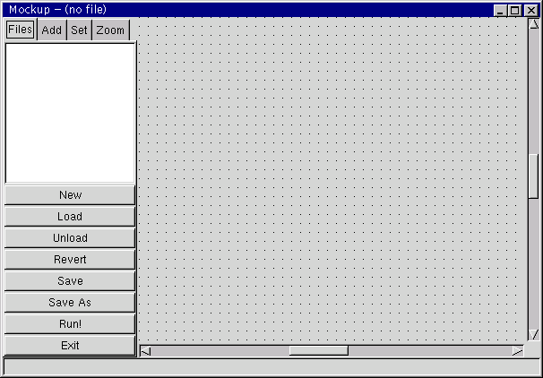
A window should come up that looks like this:
You can see several areas: the main part (with the grid on it) is the sheet where you will be placing your graphical descriptions of the blocks. To the left of it is a area with tabs on top that read "Files", "Add", "Set" and "Zoom". When selecting one of these tabs, an appropriate panel becomes visible where you can perform various actions. In the picture above, the "Files" panel is active, which is used to work with, you guessed it, files. You can load and save files, as well as running your simulation and exiting the editor.
The "Add" panel is used to add components to your block, the "Set" panel is used to set the various parameters of existing components, and the "Zoom" panel is used to navigate around a large sheet.
The next thing to do is to create the impulse-source block.
You can have multiple files open at the same time, and the "Files" panel can be used to switch between them. Right now, no file has been loaded into the editor, so the list of files is empty. We are going to create a new file, so click on "New" in the "Files" panel. A new entry should appear in the list, named "(unamed)".
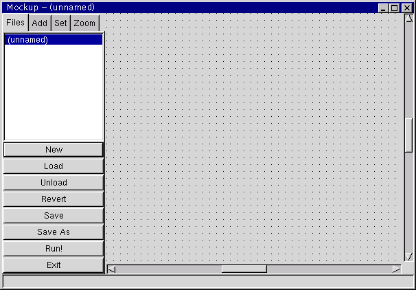
The new file has been selected automatically, as can be seen in the title of the window.
We will now give the file a real name by saving it to disk. Click on "Save" and specify a name of "impulse-source.block". The extension is very important, make sure it is ".block". Note how the entry in the file list changes to "impulse-source", which is the name of the new block as it has been derived from the file name and that the title of the window shows the real file name.
Next, we are going to add two components to the schematic. To do this, click on the "Add" tab to go to the "Add" panel. Select "example" from the first list, and then "source" from the second list. When you now move the mouse into the sheet area, a component should follow it.
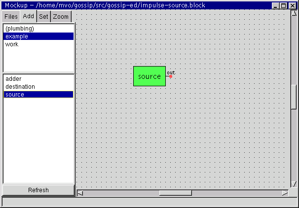
Place that component on the sheet by clicking the left mouse button.
The first list shows all libraries that are accessible. When a library has been selected, the second list shows the blocks contained in it. The editor is not always up to date, but clicking the "Refresh" button will cause it to synchronize with reality.
Select the "source" block again from the second list, and place a second "source" component on the sheet.
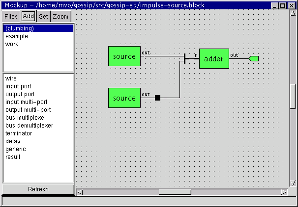
Next, add an "adder" block from the "example" library to the sheet and an "output port", a "delay" and a "bus demultiplexer" from the "(plumbing)" library. It should then look like this:

You can move components around by bringing the mouse over them, depressing the left mouse button, dragging the mouse and releasing the mouse button again.
The green boxes represent components of Gossip blocks, the red dots are places where wires can be connected, and the rest are special purpose elements from the plumbing library. The plumbing library is not a real Gossip library, it exists only to hold the things that are needed for a graphical description of hierarchical blocks.
When you now change back to the "Files" panel, you will see that the "impulse-source" entry in the file list is followed by a star "*". This indicates that the file has been modified and needs to be saved.
We will now add the wires to the schematic. Depress the left mouse button on one of the red dots and drag the line that appears to another red dot that you want to connect to. You can keep the button pressed and release it over the second dot or you can immediatly release it over the first dot, and click again on the second dot. When you have made a connection, the red dot will disappear.
To make a wire that consists of multiple segments, like the one from the delay to the bus demultiplexer, you click the left mouse button where you want the new segment to start.
While dragging out a line, clicking the middle mouse button will undo the last step. It is probably best to play with wires and components a little bit to find out what you can do with them. One thing that should probably be noted here is that you can directly connect two red dots while placing components on the sheet. They will be automatically connected with a wire then.
To delete elements from the sheet, place the mouse over them and press the right mouse button. A menu will appear where you can choose "Delete".
When all connections have been made, the sheet should look like this:
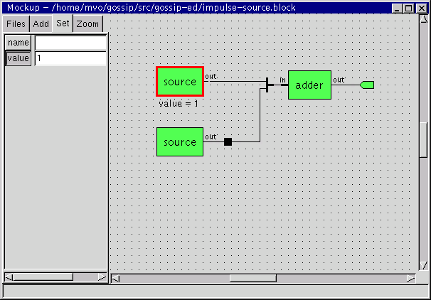
As the last step, we need to set the parameters of some of the elements. We do this by using the "Set" panel.
Select the first "source" component (the one without the delay in its output). Selecting a component is done by clicking on it with the left mouse button without moving the mouse.
Then, enter "1" for the "value" parameter and click on the "value" toggle-button so that it is depressed. Activating the toggle-button will make the setting for "value" appear on the sheet itself.
Do the same thing for the second source, but use "-1" for "value" this time.
Next, set the "delay" parameter of the delay element to "1", and the "name" of the output port to "out".
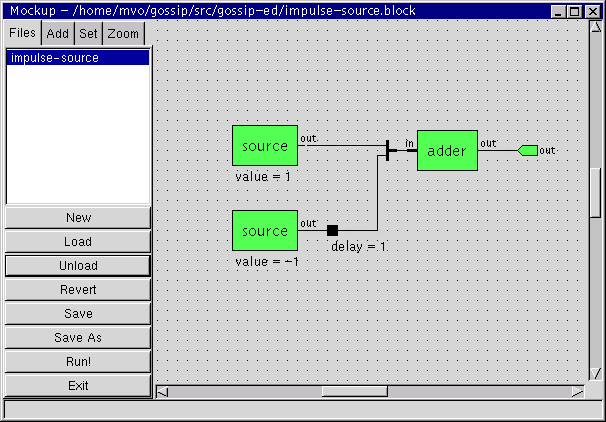
This completes the creation of the impulse-source block. Change to the "Files" panel and click on "Save" to save your changes. The star will disappear from the entry in the file list and the final display should look like this:
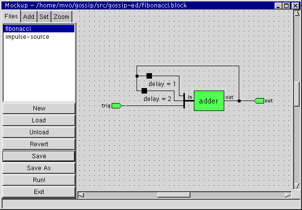
Using the techniques from above, create a second block named "fibonacci" that looks like the following snapshot.
Additionally, you might want to know the following: to make a bus demultiplexer with three taps, use the context menu of the multiplexer and chosse "Grow 1". To connect wires together so that they form the black dots shown in the screenshot, you first place an `invisible' dot by making a wire with multiple segments and then click the middle mouse button on such an invisible dot. The invisible dots will light up in red when you move the mouse over them. [Yes, I know this is complicated. Maybe I should expand this section into multiple steps.]
Don't forget to set the names of the input and output ports.
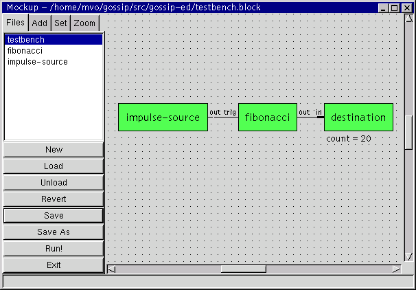
Now that both the impulse source and the Fibonacci generator blocks have been created, we need to put them to work in a testbench. A testbench is also a block, but one without any input or output ports.
Like always, start by clicking "New" in the "Files" panel. Save the new block as "testbench.block".
Then, change to the "Add" panel and select the "work" library. The "work" library will contain the blocks in the current working directory, that is, the directory where the editor has been started in. It will probably not contain our new blocks yet. In any case, click the "Refresh" button just to make sure everything is up to date. Reselect the "work" library afterwards. Now you should see both the "fibonacci" block and "impulse-source" block.
Add them to the testbench sheet and connect them with wires until it looks like the following snapshot. The "destination" components comes from the "example" library.
Save the file, and click on "Run!" in the files panel. The simulation should run and produce the first twenty Fibonacci numbers.
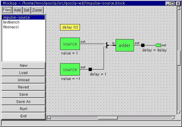
To experiment with changing existing blocks, we are now going to add a generic to the impulse-source that specifies how much the impulse on its output should be delayed.
To do that, change to the "impulse-source" block by using the file list in the "Files" panel. Then, using the "Add" panel, add a "generic" from the "(plumbing)" library. Select the generic (a little yellow box), and set the name to "delay" and the default to "0".
Furthermore, delete the wire from the output of the adder to the output port with the contect menu of the wire and add a delay element in its place. Set the "delay" parameter of the delay element to "delay". Save the block. The result should look like this:
Now, activate the "testbench" file. It contains an impulse-source, but it is still the old version. Running a simulation will always use the newest version, so there are likely to be cryptic error messages when you click on "Run!", in general. (In our case, however, the interface of impulse-source has changed compatibly, so everything is alright.)
To replace the impulse-source with its newer version, you have to click on "Refresh" in the "Add" panel, delete the old component and add a new one. There will be a more convenient way to do this in the future, of course.
Once you have done this, selecting the new impulse source will reveal the "delay" generic in the "Set" panel. Set it to "5", for example, save the testbench, and click on "Run!". The Fibonacci numbers should now be preceeded by five zeros, because the trigger comes five data elements later.
And don't forget: this is only a mockup! If you have suggestions how to improve it, please tell us.